
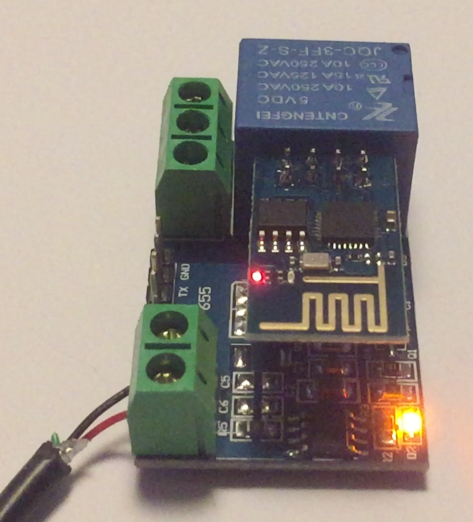
This is a HW-655 relay board designed to work with an ESP-01, the nifty tiny embedded WiFi device. It appears to be a clone of a China LC Technology ESP8266 5V WiFi relay module. I found some documentation here and some more details of a similar product from the same vendor here. I also found warnings that some clones did not have programmed STM8 micro controllers so they don’t work.
The missing element in trying to make this device work was the concept that you control the relay by transmitting serial characters from the ESP-01 rather than controlling an OUTPUT pin. There is a STM8 micro controller on the board. Why do this? I’m not sure but it does leave a couple of IO pins you can solder to. One theory is it ensures the relay doesn’t close without something quite deliberate happening in the ESP-01 which could prevent the ESP-01 crashing and leaving your controlled device powered.
The magic string is four bytes long.
A0 01 01 A2 causes the relay to CLOSE.
A0 01 00 A1 causes it to OPEN.
It’s probably a good idea to flush out any crud in the serial port before you send the string. I have noticed that A0 01 A0 01 01 A2 doesn’t cause the relay to CLOSE.
I wanted to test my relay module to see if it was programmed since it was obviously a clone. I couldn’t enter the four byte sequences in my terminal emulator so I wrote a bit of Perl on my Mac:
$| = 1;
printf("Close");
sleep 1;
printf(chr(0xa0) . chr(0x01) . chr(0x01) . chr(0xa2) ); # close
sleep 1;
printf("Open");
sleep 1;
printf(chr(0xa0) . chr(0x01) . chr(0x00) . chr(0xa1) ); # open
sleep 1;
And ran it like this:
perl < relay-close.pl > /dev/cu.usbserial-A703EA9U
While monitoring the serial being sent like this:
cat /dev/cu.usbserial-A703EA9U | hexdump
0000000 43 6c 6f 73 65 a0 01 01 a2 4f 70 65 6e a0 01 00
0000010 a1 43 6c 6f 73 65 a0 01 01 a2 4f 70 65 6e a0 01
And it worked! (Actually the codes I found online were Open: A0 01 01 A2 and Close: A0 01 00 A1 which are backwards!)
The ESP-01 has an ESP8266 system on chip and some flash. It is also Arduino compatible so you can write C++ code that will execute directly on the device. The next problem is 00 is NULL and strings are terminated with a NULL in C languages so you have apply a bit of effort like:
void setup() {
  Serial.begin(9600);
}

void loop() {
 Serial.write("\xa0\x01\x01\xa2"); // CLOSE RELAY
 delay(1000);
 Serial.write("\xa0\x01"); // OPEN RELAY
 Serial.write(0x00); // null terminates a string so it has to be sent on its own
 Serial.write(0xa1);
 delay(1000);
}
I compiled it for a board type of ESP8266 and uploaded it via my handy little ESP-01 programmer.

Then plugged the ESP-01 into the HW-655, applied power and the relay will happily turn on and off every second forever.
The ESP-01 is quite clever and can be loaded with some off the shelf firmware that does WiFi and can listen for a TCP connection so you could open a socket and send the four byte sequences from a machine on the same network. If you do some digging you will find some projects using some of Espressif’s IoT tools that let you control these devices from your mobile phone.
Note that there are two versions of the ESP-01. If you’re blowing $3 of your hard earned cash on one or five you should probably buy ESP-01S modules with 1MB of flash rather than the ESP-01 with only 512K of flash. You need the bigger memory for Version 1.5 of the AT “modem” firmware which can remember WiFi and TCP settings.
Other differences between ESP-01 and ESP-01S found online:
– blue PCB vs black
– 512kB flash vs 1MB
– Red power LED vs -No- power LED
– Blue LED on GPIO1 (TX) vs GPIO2 (and low = on)
The difference in LED may cause confusing when using BUILTIN_LED in the Ardunio IDE because the IDE expects the LED on GPIO1 (TX) and it’s inverted so OFF is lit and ON is dark.
