DIY Offgrid Project – Battery Management System and Contactor

This box of stuff will protect the battery in my home brew 23kwh storage system. Given the failure modes for lithium batteries involve dying permanently and catching fire you want to get this right. This will be able to stop the inverters from draining the battery and if things get really outside the comfort zone it will disconnect the battery completely. I could disconnect the solar panels from the inverters if I needed an absolute override for high voltage but I don’t think that’s going to be a problem.

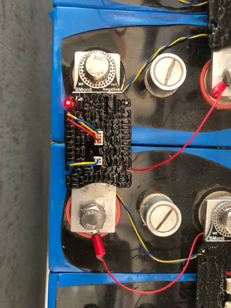
The Batrium BMS is the brains of the operation.

The big thing on the left is the contactor. It’s designed for forklifts. It’s rated at 48 volts 200 amps DC. It came via AliExpress.

The relay coils are also 48 volt DC although the contacts aren’t really rated for that many volts. I’m not expecting problems because the main contactor draws only two hundred milliamps which isn’t going to sustain much of an arc.

If either relay is closed the contactor will close. The BMS has a pair of FET outputs that connect to ground when enabled. One is programmed as Charge OK and the other as Discharge OK. They can also be set to open and close a bistable contactor but thats not what I have and they scare me.

I designed everything using a sketch tool on my ipad called You Doodle.

Then I started to put it together. Here’s the result so far.

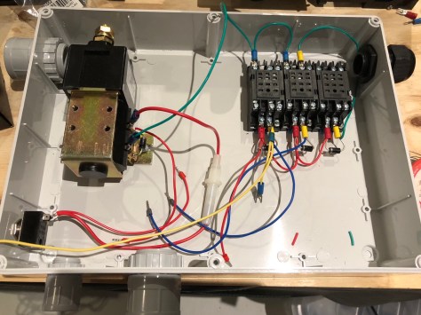
Next task is making the aluminium strap between the contactor and the current shunt. Then I’m ready to bolt it all to the wall.

UPDATE

Here it is mounted to the wall:

IMG_1191.jpg

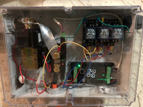
Note the shunt is operating BACKWARDS. There is a setting in the shunt setup window that tells the WatchMon that the shunt is reporting backwards.

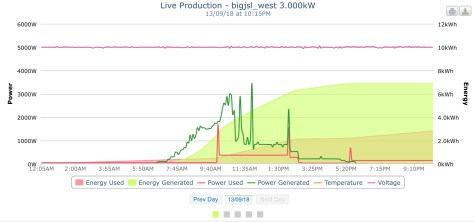
After I reassembled everything I got really wildly fluctuating readings in the tool.

Pulling everything apart I discovered that one of the two brass screws that hold the sensor to the shunt and carry the voltage from the shunt to the sensor was loose. I probably put too much force on the sensor when wrangling everything into place.

One day I may replace that awful ugly aluminium bar. I went to the trouble of twisting it so you can see the LEDs but then I discovered that they are visible through the side of the sensor too! Sadly twisting it made it less than pretty.

Another interesting observation is that the contactor runs very hot. I know the EV community have used various circuits to reduce the average hold current on the contactor but it’s probably easier to put a little fan in the side of the box.

DIY Offgrid Project – Monitoring

If you are a fan of solar power you have probably heard of pvoutput.org, a cloud service that records and graphs the generation and consumption of member’s renewable energy systems.

The new system is graphed here. If you hunt around you can find my existing grid-tied system too. As of writing, with 3kw of panels and running the pool pump and garden lights, a day looks like this:

IMG_1111.jpg

Power is measured in watts “w”. Energy is power over time and the unit often used for electricity is kilowatt hours “kwh”, which is 1,000 watts for 1 hour. It’s also 2,000 for half an hour or 500 watts for 2 hours.

The dark green line is the power out of the solar panels that is charging the battery and running the inverter loads. The red line is the power consumed by loads and the overhead of the inverter itself which is around 50 watts, around 1.2kwh per day. The large green area above the pink “energy used” is the effective energy overheads of the system and losses while the charger tries to “balance” the battery pack. At present I appear to be wasting about 4kwh per day which is quite high when you stop and think about the maximum 20kwh per day the solar panels can produce. That said, my methodology is a little primitive.

The PIP inverter has an RS232 serial port which is “normal” for IT 20 years ago but unusual for solar kit these days where RS485, MODBUS or CAN are much more common. You need to talk at 2400 bits per second, 8 data bits, no parity and 1 stop bit. The protocol has been documented and I found some Python code to talk to the inverter in the AEVA PIP forum but it is for loading data into a database.

Data available includes the voltage and amps from the solar panels, the battery voltage and charge current in integer amps and the voltage and watts being supplied by the inverter to loads.

I cleaned up the existing code that reads the data about once every 1.5 seconds and wrote some that does some maths and logic and then uploads the data to pvoutput every five minutes. You can find my code stashed away on that forum.

I multiply PV volts by amps to get watts which is legitimate for direct current.

I multiply that by the duration in hours since the last sample (about 1.5 seconds but measured to microsecond accuracy by the RasberryPi) to give watthours.

I do the same for the inverter load which is reported in watts (and also in volt amps which is probably a source of discrepancy for those of you who understand reactive loads).

All of this is summed and then uploaded on the first sample after the wall clock minutes are integer divisible by 5. (Remember modulo?)

The next extension to the code is to listen to the Batrium BMS and upload the StateOfCharge% and net current in or out of the battery from it. It’s much more accurate than the integer amps from the PIP inverter.

DIY Offgrid Project – Integration Part 2

Lithium Iron Phosphate batteries like all lithium batteries need a battery management system to protect the individual cells from being over charged or over discharged.

This is a Batrium M8 Cellmon.

It connects to a monitoring box that has an embedded computer. In turn there is some software that only runs on a Windows machine that visualises the performance of the battery.

If a cell reaches maximum safe voltage before the others have fully charged the pack will not be fully charged. The red bits are the cellmons that are “by-passing” which means they are attempting to limit the voltage across their cell in an attempt to “balance” the voltages across all the cells. They can do this for about 1 amp which means it will take a while before the battery pack is fully “top balanced”. I can help this process along by discharging a high cell with a load like an incandescent headlight bulb. But during the main part of the charge and discharge cycle the cells are all at much the same voltage so the real imbalance is relatively small.

DIY Offgrid Project – MC4 Fuses

Solar PV panels are wired in series to get to the desired voltage and then these “strings” are connected in parallel to deliver the required current. Each string is supposed to have a fuse in series to protect against excessive current flowing through the string. Solar panels have several characteristics including an open circuit voltage (Voc) and a short circuit current (Isc) Isc which is typically the maximum current the panel and hence string can produce. Deployment rules require a protective fuse in series. The panels I’m using say the fuse should be no more than 15 amps. My panels can’t produce more than 10 amps so the output of the panel isn’t going to blow the fuse.

What is the fuse protecting? It’s protecting the panels from being damaged by being back-fed from several other strings and also from damage your inverter fails and drives a high current back through the panel. It is also protecting the cabling from excessive current although I’m using 4mm² cable which is rated to carry 25 amps. You have to try hard to imagine the failure scenarios on a low voltage system like mine that would cause the fuse to blow. Never the less, I have one of these fuses in series with each string of three panels.

Having wired three strings of three panels, with fuses in-line, I short-circuited them to test performance.

Nearly 20 amps Isc – short circuit current. Not bad for late in the day!

And a word of warning. These were advertised as “fuse diodes” but there is nothing “diode” about them so don’t pay a premium for that.